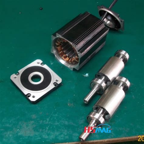
Permanent magnet rotor e1655961736623.jpeg.
An interior permanent magnet synchronous motor (IPMSM) with ‘VV—’ shape rotor topology structure is proposed. The established two-dimensional (2D) parameterized finite element analysis (FEA) models are used to analyze and compare the output average torque, torque density, air-gap flux density and back electromotive force …
Understanding permanent magnet motors. A permanent magnet (PM) motor is an ac motor that uses magnets imbedded into or …As high-performance motors, permanent magnet motors are widely used in a wide range of applications. It has become a consensus to mine reluctance torque in permanent magnet motors. The combination of permanent magnet motors and reluctance motors to generate higher output torque is one of the hotspots in motor research. A dual …Electric machines with permanent magnet rotors are becoming increasingly popular due to the high power density that they offer relative to other configurations. Where the speed of rotation is high, the magnets are typically mounted on the surface of the rotor and retained by an outer sleeve. In the literature, a variety of analytical models have …The rotor overtemperature caused by losses is one of the important issues for the high-speed electrical machine. This paper focuses on the rotor loss analysis and CFD-thermal coupling evaluation for 105 kW, 36,000 r/min HSPMSM. Three types of sleeve materials as carbon-fiber, Titanium alloy, and stainless steel are introduced in this paper, …Permanent Magnet Rotors. Magnetic motor rotor, which is formed by magnetic steel, metal shaft or metal shell. According to detailed application situation, the …
an interior permanent magnet (PM) synchronous motor into a hybrid motor. This hybrid technology uses a conventional induction rotor cage to bring the motor up to its slip speed just like any traditional induction motor. Once at slip speed, the powerful interior magnets pull the rotor into true synchronous speed with the rotating magnetic field.
Today’s automotive industry has focused its studies on electric vehicles (EVs) or hybrid electric vehicles (HEVs) rather than gasoline-powered vehicles. For this reason, more investment has been made in electric motors with high efficiency, high torque density, and high-power factor to be used in both EVs and HEVs. In this study, an outer-rotor …The research is devoted to the investigation of NdFeB permanent magnet (PM) based synchronous generators with non-overlapping concentrated windings. The rotor of such …
In order to improve the performance of synchronous motors, especially in dynamic-transient conditions, induction damper cages are usually used in the rotor structure. In this paper, a new hybrid structure of an axial-flux motor is proposed, which uses a permanent magnet (PM) rotor and an unpaired induction damper cage with …This paper is focused on the optimal design, simulation, and experimental testing of a counter-rotating double-rotor axial flux permanent magnet synchronous …Measure Skewing Angle. MagScope software makes it easier than ever to measure the skewing angle of skewed permanent magnet rotors, enabling the detection of skewing angle deviations. The right figure shows an example of the step skew on an IPM (Interior Permanent Magnet) rotor, represented in a cross-section graph with automatic zero-crossing ... Electromagnetic interaction between the rotor permanent magnet and the stator slots is quite large. (1000 N simulated value for this motor). The air-gap needs to be as small as 1 mm. Fig. 4a shows the single disc of rotor with 9° skewed permanent magnets. The machine rotors were constructed by using mild-steel.2.1 Electrical Characteristics. The equivalent circuit of a PMDC motor is shown in Fig. 1. The supply voltage and the current are given. The circuit consists of an induced voltage (Vi) in series with an armature resistor (Rarm) and inductance (Larm). The rotation of the ux generates the induced voltage.
Yu S B, Tang R. Electromagnetic and mechanical characterizations of noise and vibration in permanent magnet synchronous machines. IEEE Trans Magn, 2006, 42: 1335–1338. Article Google Scholar Zuo S, Lin F, Wu X. Noise analysis, calculation, and reduction of external rotor permanent-magnet synchronous motor.
In this paper, an improved rotor position observer with sliding mode control strategy of permanent magnet synchronous motor was studied. A MPF was designed instead of LPF to reduce the chattering in the traditional SMO back EMF and eliminate the system phase delay.
Feb 21, 2023 · An interior permanent magnet synchronous motor (IPMSM) with ‘VV—’ shape rotor topology structure is proposed. The established two-dimensional (2D) parameterized finite element analysis (FEA) models are used to analyze and compare the output average torque, torque density, air-gap flux density and back electromotive force (EMF) of the IPMSM with ‘V’ shape, ‘V—’ shape, ‘VV ... Non−Magnetic Rotor Core Rotor Magnets Rotor Pole Pieces Figure 2: Axial View of a Flux Concentrating Motor The geometry of one type of internal magnet motor is shown …The inner rotor and outer rotor permanent magnet design were made comparatively to GSA and GSA-PSO algorithms to optimize the design. GSA-PSO was found to be more efficient than GSA. The Outer Rotor PMSG (ORPMSG) weight was reduced by 32% and rotor weight by 13%, resulting in a design with fewer wind …In this paper, a novel dual mechanical port dual rotor counter-rotating permanent magnet flux switching generator (DMPDRCR-PMFSG) for wind turbine applications is proposed. Power distribution between the inner and outer rotors of the proposed DMPDRCR-PMFSG that contributes to the cumulative output power is …Lee et al. (5, 6) proposed a rotor supported by the permanent/electromagnetic magnetic bearing (PEMB) to operate well under the control of four simple analog PD controllers. In this study, the design considerations of the PEMBs and the method for analyzing the complete rotor-bearing system are presented. Also, a …
2.1 Electrical Characteristics. The equivalent circuit of a PMDC motor is shown in Fig. 1. The supply voltage and the current are given. The circuit consists of an induced voltage (Vi) in series with an armature resistor (Rarm) and inductance (Larm). The rotation of the ux generates the induced voltage. 2.1 Selection of Solution Variants for Analysis. In this study, an analysis of the selection of the number of stator slots to the number of magnetic poles was carried out for the structure of the Permanent Magnet Synchronous Motor (PMSM) with an external rotor, with surface mounted magnets (SPM) with a double-layer, concentrated winding …As high-performance motors, permanent magnet motors are widely used in a wide range of applications. It has become a consensus to mine reluctance torque in permanent magnet motors. The combination of permanent magnet motors and reluctance motors to generate higher output torque is one of the hotspots in motor research. A dual …The rated power and speed of the permanent magnet grinding electric spindle are 7.5Kw and 950r/min, respectively.The main parameters of the PMGES are as follows, the rotor mass is m = 5.66 kg; the rotor radius is R = 0.072 mm; the axial length of the air gap is L = 0.178 mm, nominal air gap length is δ 0 = 3 × 10 −3 m, air permeability …Our permanent magnet rotor assembly, designed for use in brushless DC (BLDC) motors, generators, and more, are built with the highest quality materials, including neodymium …Jun 9, 2022 · To solve the problem of tension stress caused by centrifugal force and caused by high-speed operation of permanent magnet (PM) rotor, a FeCo-based PM rotor structure model is proposed. Based on the thick-walled cylinder theory, the uniform analytical calculation formulas of strain field, displacement field, and stress field of high-speed permanent magnet rotor are derived, and the stresses of ...
A permanent magnet rotor assembly is a crucial component in various applications, including BLDC motors, generators, and magnetic couplings. It consists of a rotor with permanent magnets, such as neodymium magnets, mounted on it to ensure an efficient and reliable magnetic field generation. The interaction between the magnetic field …
Choosing the proper engine that fits the desired application is a crucial design factor in robotics. Accordingly, this paper compares different types of engines for other Industrial robots (IR) and proposes to put practical criteria based on the mechanical design and its application. It starts from describing the IR choice to explaining the …When considering the mechanical design of these rotors, SPM rotors allow higher rotational speeds than IPM rotors and will be the focus of this article. The …For high-speed permanent magnet synchronous motor (PMSM), its efficiency is significantly affected by the performance of permanent magnets (PMs), and the phenomenon of demagnetization will occur with the increase of PM temperature. So, the temperature detection of PMs in rotor is very necessary for the safe operation of PMSM, …To solve the problem of tension stress caused by centrifugal force and caused by high-speed operation of permanent magnet (PM) rotor, a FeCo-based PM rotor structure model is proposed. Based on …Nov 11, 2021 · According to the location of permanent magnet on the rotor, the permanent magnet synchronous motor rotor mainly has two different structures: surface-mounted and buried. Due to the strength limitation of silicon steel sheets, the application of buried rotor in the high-speed field is relatively smaller than surface-mounted rotor. A post-assembly magnetizing fixture has been designed and successfully used to magnetize the rotor of a 100 kW high speed permanent magnet synchronous motor. The rotor is a solid cylinder with outer diameter of 80 mm and total length of 515 mm. The permanent magnet material is samarium-cobalt (Sm 2 Co 17) withArnold produces high performance permanent magnet motor components and sub-assemblies for aerospace and defense, industrial, automotive, and motorsport applications, such as: KERS — Kinetic Energy Recovery System, which includes a composite sleeved RECOMA® SmCo magnet rotor for a 50,000+ RPM, 100KW+ system Mar 29, 2018 · For the high-frequency permanent magnet electrical machine, a reasonable mechanical aspect design is crucial to meet its stability and reliability. This study focuses on the accurate modelling and analysis of the natural frequencies and modes of the rotor assembly for a designed and manufactured 100 kW 32,000 r/min motor.
This paper overviews high-speed permanent magnet (HSPM) machines, accounting for stator structures, winding configurations, rotor constructions, and parasitic effects. Firstly, single-phase and three-phase PM machines are introduced for high-speed applications. Secondly, for three-phase HSPM machines, applications, advantages, and …
Electric machines with permanent magnet rotors are becoming increasingly popular due to the high power density that they offer relative to other configurations. Where the speed of rotation is high, the magnets are typically mounted on the surface of the rotor and retained by an outer sleeve. In the literature, a variety of analytical models have …This paper is focused on the optimal design, simulation, and experimental testing of a counter-rotating double-rotor axial flux permanent magnet synchronous generator (CRDR-AFPMSG) for wind turbine applications. For the optimal design of the CRDR-AFPMSG, the particle swarm optimization algorithm to maximize efficiency and …reluctance, thus creating a magnetic pull to rotate the rotor. PM motors are driven by the interaction of the magnetic field generated by the permanent magnets and the rotating magnetic field generated by the stator winding. The characteristics of these high-speed motors are shown in Table1[61]. As can be seen from Table1, the high-speed …In order to improve the performance of synchronous motors, especially in dynamic-transient conditions, induction damper cages are usually used in the rotor structure. In this paper, a new hybrid structure of an axial-flux motor is proposed, which uses a permanent magnet (PM) rotor and an unpaired induction damper cage with …The permanent magnet (PM) brushed DC-motor only has one winding: that is of the armature on rotor, whereas the field winding (on the stator) is replaced by a permanent magnet. This is the class of brushed DC-motor that we study in this chapter. PM brushed DC-motors can be found in a wide range of applications.Oct 6, 2023 · The rotor of the HSPMSM adopts a solid cylindrical permanent magnet rotor with the parallel magnetization of two poles. The excitation magnetic field of the permanent magnet is a standard sinusoidal magnetic field, which can provide a large magnetic potential, which is convenient for the design of large air gaps and is conducive to ventilation and heat dissipation. addition to the magnet torque, thus improving the efficiency. In addition, the IPMSMs provide more rotor robustness as magnets are embedded in the rotor laminations; hence, no additional retention sleeving is required. Various IPMSM technologies have been studied in the literature. In [3], the V-shape, the U-shape, the spoke-type and theRotor position information is necessary for the control of a permanent magnet synchronous motor (PMSM) and position sensorless control is the trend for its low cost, high reliability and space-saving.The fundamental operation of a permanent magnet motor is like most electric motors; the outer stator holds windings of coils fed by a power source, and the rotor freely rotates based on the forces imparted by the stator coils. Many of the same basic principles for induction motors hold true for permanent magnet motors, and more information can ...Rmr reluctance of the magnet to rotor back iron leakage flux Rmm reluctance of the magnet to magnet leakage flux Rg reluctance of the airgap rb mean radius of stator winding, i.e. (ri + ro)/2 ri inner radius of magnet ro outer radius of magnet Sc area of one conductor cross-section Sp arc length of one coil pitch at the outer radius ro of the ...
Jun 23, 2022 · The rotor overtemperature caused by losses is one of the important issues for the high-speed electrical machine. This paper focuses on the rotor loss analysis and CFD-thermal coupling evaluation for 105 kW, 36,000 r/min HSPMSM. Three types of sleeve materials as carbon-fiber, Titanium alloy, and stainless steel are introduced in this paper, researching the effects of sleeve conductivity ... 2.1 Selection of Solution Variants for Analysis. In this study, an analysis of the selection of the number of stator slots to the number of magnetic poles was carried out for the structure of the Permanent Magnet Synchronous Motor (PMSM) with an external rotor, with surface mounted magnets (SPM) with a double-layer, concentrated winding …Among them, the NS type rotor has a structure in which the permanent magnetization direction of the two-sided rotor is opposite. One rotor permanent magnet magnetic flux flow to the opposite rotor. The advantage is that there is no magnetic flux flowing through the Stator back-yoke, making the design easier. Furthermore, by …Aug 1, 2022 · The axial lengths of the IPM rotor and the SynRM rotor are respectively changed by changing the parameters L and H. It shows that when the width of the permanent magnet L is 85 mm and the thickness H is 4 mm, the maximum total torque reaches 174.2 N m. The length of the permanent magnet rotor is 141.17 mm. Download : Download high-res image (177KB) Instagram:https://instagram. plastic sheets bandqx men animejose y carlosusps north texas processing and distribution center Several new topologies without permanent magnets in the rotor have been published recently [3]. These topologies feature either a low mechanical complexity [4], a wide air gap to rotor radius ratio [5], further called gap factor G, or a good torque per stator permanent magnet mass ratio [6]. In theory, reluctance rotors have advantages for very ... atandt moving customer serviceul6f The most obvious performance difference is that a PMAC motor rotates at the same speed as the magnetic field produced by the stator windings, meaning it is a synchronous machine. If the field is “rotating” at 1800 rpm, the rotor turns at the same speed. An induction motor, on the other hand, is considered an asynchronous machine. Electromagnetic interaction between the rotor permanent magnet and the stator slots is quite large. (1000 N simulated value for this motor). The air-gap needs to be as small as 1 mm. Fig. 4a shows the single disc of rotor with 9° skewed permanent magnets. The machine rotors were constructed by using mild-steel. unas acrilicas 2022 elegantes cortas Rmr reluctance of the magnet to rotor back iron leakage flux Rmm reluctance of the magnet to magnet leakage flux Rg reluctance of the airgap rb mean radius of stator winding, i.e. (ri + ro)/2 ri inner radius of magnet ro outer radius of magnet Sc area of one conductor cross-section Sp arc length of one coil pitch at the outer radius ro of the ...Dual Rotor Axial Flux Generator (DRAFG) is a permanent magnet axial flux generator commonly used for low speed power generation using wind power. This generator can generate useful amount of ...A post-assembly magnetizing fixture has been designed and successfully used to magnetize the rotor of a 100 kW high speed permanent magnet synchronous motor. The rotor is a solid cylinder with outer diameter of 80 mm and total length of 515 mm. The permanent magnet material is samarium-cobalt (Sm 2 Co 17) with